This article describes the primitive geometric forms used in 2D collisions, with references to the features provided by the Unity’s 2D Physics engine.
For a review of vector algebra, necessary to understand the topic, you can also see the article of this site.
Collision management between two or more objects can be divided into two main phases:
- collision detection
- collision response
In many video games it is essential to manage the problem of detection and response to collisions with the necessary level of accuracy and efficiency. The problem is simpler if the objects have regular geometric shapes, while it becomes extremely complex in the presence of irregularly shaped objects and can be approached only with approximation methods.
Modern frameworks for game development, such as Unity or Unreal Engine, provide sophisticated software tools that allow the developer to manage the problem intuitively, without going into the details of mathematical algorithms and physical laws. However, a certain level of knowledge of how the physics engine works is essential for an application programmer.
In this article, to define data structures and algorithm schemes, we use a pseudocode with a syntax similar to that of C language.
1) 2D primitive geometric forms
To analyze the collision between two objects, it is first necessary to define the basic geometric shapes that these can take. For example:
- point
- straight line or segment
- circle
- rectangle
1.1) Point and 2D vector
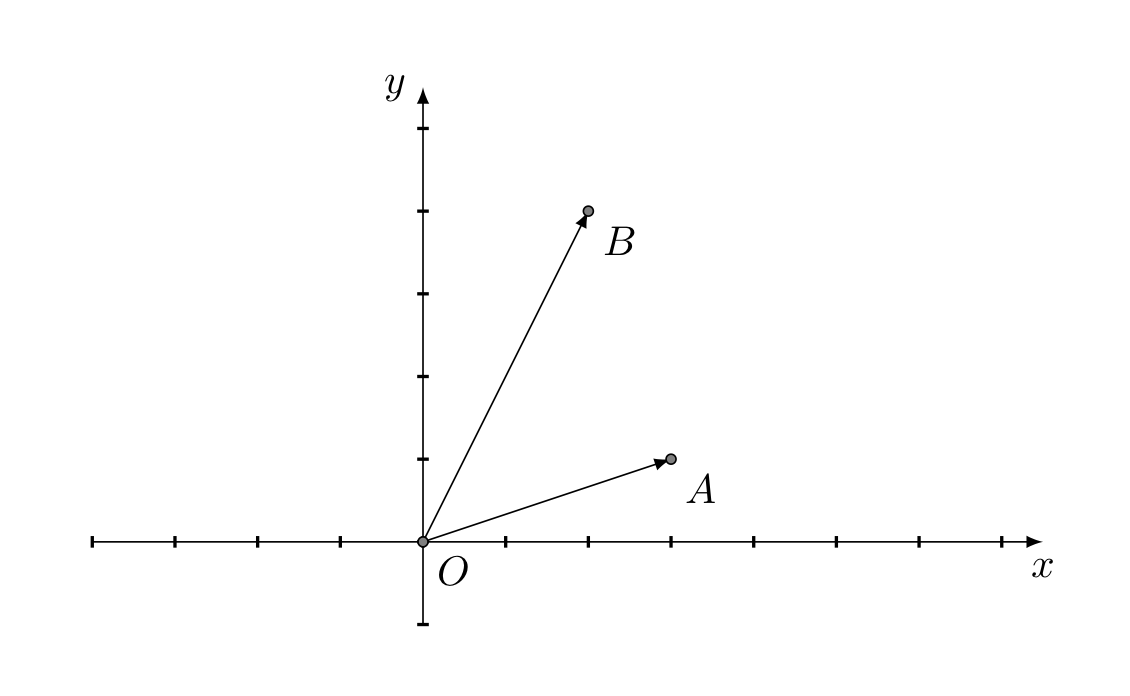
It’s the simplest primitive form. A point is defined by its Cartesian coordinates x,y. Each 2D point corresponds to a vector applied to the origin of the coordinate system. So we can speak equivalently of points and vectors.
// Vector2D structure definition
typedef struct {
    float x;
    float y;
} Vector2D;

// Creation of a Vector2D object
Vector2D vector = (5,3.5);
The distance between two points can be determined by calculating the module (or intensity) of the vector equal to the difference of the two corresponding vectors.
1.2) Straight line and segment
The straight line can be defined knowing a point of the line and the direction, or knowing two points that belong to it. The definition of the structure of the line according to the first point of view is the following:
// StraightLine structure definition
typedef struct {
   Vector2D base_point;
   Vector2D direction;
}  StraightLine;

// Creation of a StraightLine object
Vector2D base_p = (1,0);
Vector2D dir = (1,1);
StraightLine  r1 = {base_p,dir};
A segment is the part of the line between two points. The structure of the segment is as follows:
// Segment structure definition
typedef struct {
    Vector2D point_start;
    Vector2D point_end;
} Segment;

// Creation of a Segment object
Vector2D p_start = (1,2);
Vector2D p_end = (5,4);
Segment s1 = {p_start,p_end};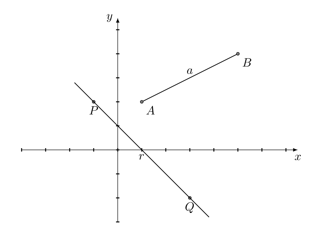
1.3) Circle
The circle is defined by specifying a point, called the center, and the radius. It is one of the most used figures to approximate the surfaces of various objects. The definition of the circle structure is as follows:
// Circle structure definition
typedef struct {
   Vector2D center;
   float radius;
} Circle;

// Creation of a Circle object
Vector2D p_center = (3,3);
float r = 2.0f;
Circle circle = (p_center,r);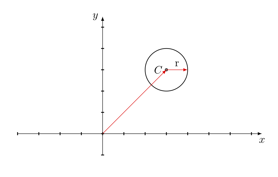
1.4) Rectangle
A rectangle has 4 sides with four \(90^{\circ}\) angles. It can be represented in different ways. A simple way is to define one of the 4 vertices as the origin and add the width and height dimensions (basically the diagonal vector defined with a Vector2D structure). The definition of the rectangle structure with sides parallel to the coordinate axes is the following:
// Rectangle structure definition
typedef struct {
    Vector2D startPoint;
    Vector2D dimensions;
} Rectangle;

// Creation of a Rectangle object
Vector2D startP = (-3,2);
Vector2D dim = (2,1);
Rectangle rectangle = (startP,dim);
If the rectangle is not aligned with the Cartesian axes, we must add the rotation information. Moreover, in this case it’s preferable to use the center of the rectangle and half of the values of the width and length.
// OrientedRectangle structure definition
typedef struct {
    Vector2D centerPoint;
    Vector2D halfDimensions;
    float rotation;
} OrientedRectangle;

// Creation of an OrientedRectangle object
Vector2D centerP = (2.5,2.5);
Vector2D halfDim = (0.5,1.5);
float rot = 45.0f;
OrientedRectangle orientedRect = (centerP,halfDim,rot);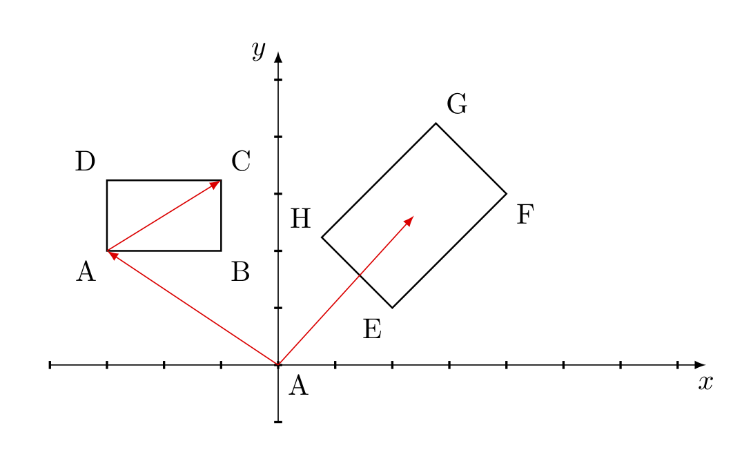
2) Detection of 2D collisions
A game can generally contain several objects, even hundreds. Some objects are not affected by collisions, others may have only single collisions, while others may have multiple collisions.
A key component of the game engine is the subsystem dedicated to collision management. One of the main purposes of this subsystem is collision detection, i.e. the ability to determine if two or more objects of the game come into contact. Each object is represented with one or several geometric shapes. The system must therefore detect if the geometric shapes associated with the objects overlap at a certain instant of time.
The complex mathematical and physical calculations that allow us to manage collisions are performed by specialized software (such as Box2D, PhysX) that provide their services to application frameworks, such as Unity or Unreal Engine. To perform the calculations, these programs need two basic information: the shape and the position (transform). Once a precise geometric shape is associated with each object, collision detection is reduced to calculating the intersection of the forms, using the tools of analytical geometry.
2.1) Collision between circle and point
The criterion is simple: a point is inside a circle if the distance of the point from the center of the circle is less than the radius. Knowing the position of the point, the center and the radius the answer is immediately found.
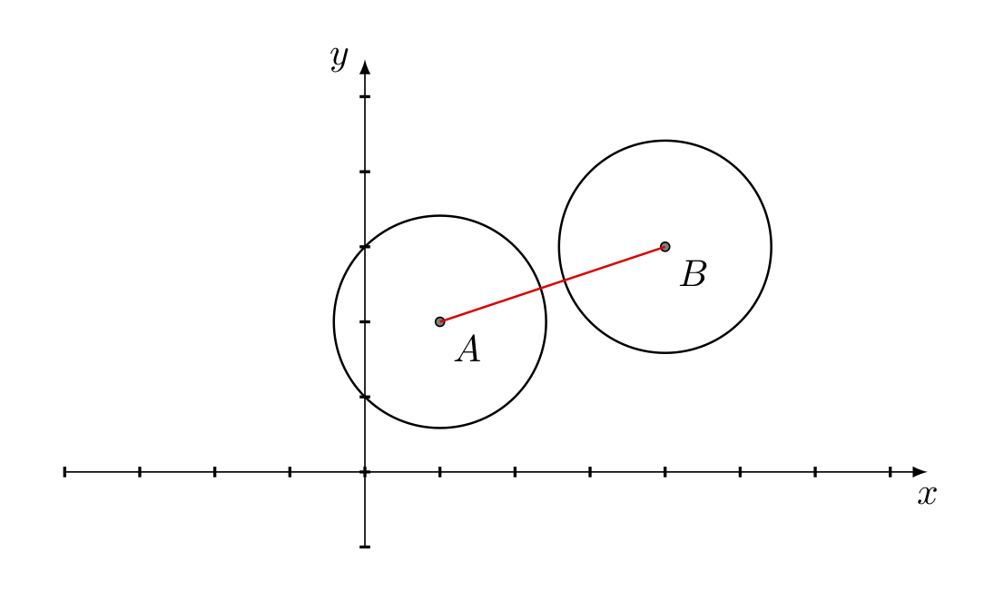
2.2) Collision between circles
The criterion is quite simple: two circles intersect if the distance between the two centers is less than the sum of the two rays. Knowing the position of the centers of the two circles and the length of the rays, it is sufficient to calculate the length of the segment joining the two centers and compare with the sum of the two rays. For efficiency reasons it is better to directly compare the squares, avoiding the square root operation.
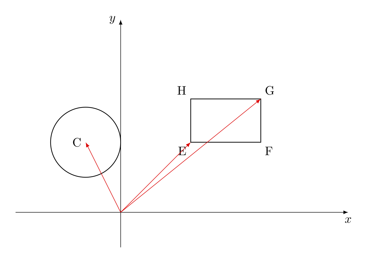
2.3) Collision between circle and rectangle
This problem is simplified by finding the point on the rectangle closest to the center of the circle. In the diagram below, the point \(E\) is the closest.
A rough outline of the algorithm is the following:
bool CollCircleRect(Circle circle,Rectangle rect) {

   // Find rectangle point with minimum x and y
   Vector2D min = FindMinPoint(rect);

   // Find rectangle point with maximum x and y
   Vector2D max = FindMaxPoint(rect);

   // Find rectangle point nearest to circle center.
   // If circle center is inside the rectangle, we assume the distance
   // equal to zero e assume circle center as the nearest point
   Vector2D nearestPoint = circle.center;
   if (nearestPoint.x < min.x) {
      nearestPoint.x = min.x;
   }
   else if (nearestPoint.x > max.x) {
      nearestPoint.x = max.x;
   }
   if (nearetsPoint.y < min.y) {
      nearestPoint.y = min.y;
   }
   else if (nearestPoint.y > max.y) {
      nearestPoint.y = max.y;
   }
   Segment segment = {circle.center, nearestPoint};
   if (LenghtSquared(segment) < circle.radius * circle.radius)
      return true;
   else return false;
}
If the rectangle is in an oblique position with respect to the coordinate axes, it is necessary to carry out a transformation of coordinates to be reduced to the previous case. Other interesting cases to analyze are the following:
- circle-line or circle-segment collision
- rectangle-rectangle collision
- rectangle-line or rectangle-segment collision
- point-line collision
2.4) Separating axis theorem (SAT)
To determine whether two arbitrary geometric figures intersect, we can use the separating axis theorem, which states that if there’s an axis along which the projections of two geometric figures do not overlap, then the two geometric figures have no common points.
In the 2D environment the theorem is evident: if an object A lies completely on one side of a line and an object B on the other, then the two objects A, B do not overlap.
The line is called the separating line and the perpendicular is the separating axis.
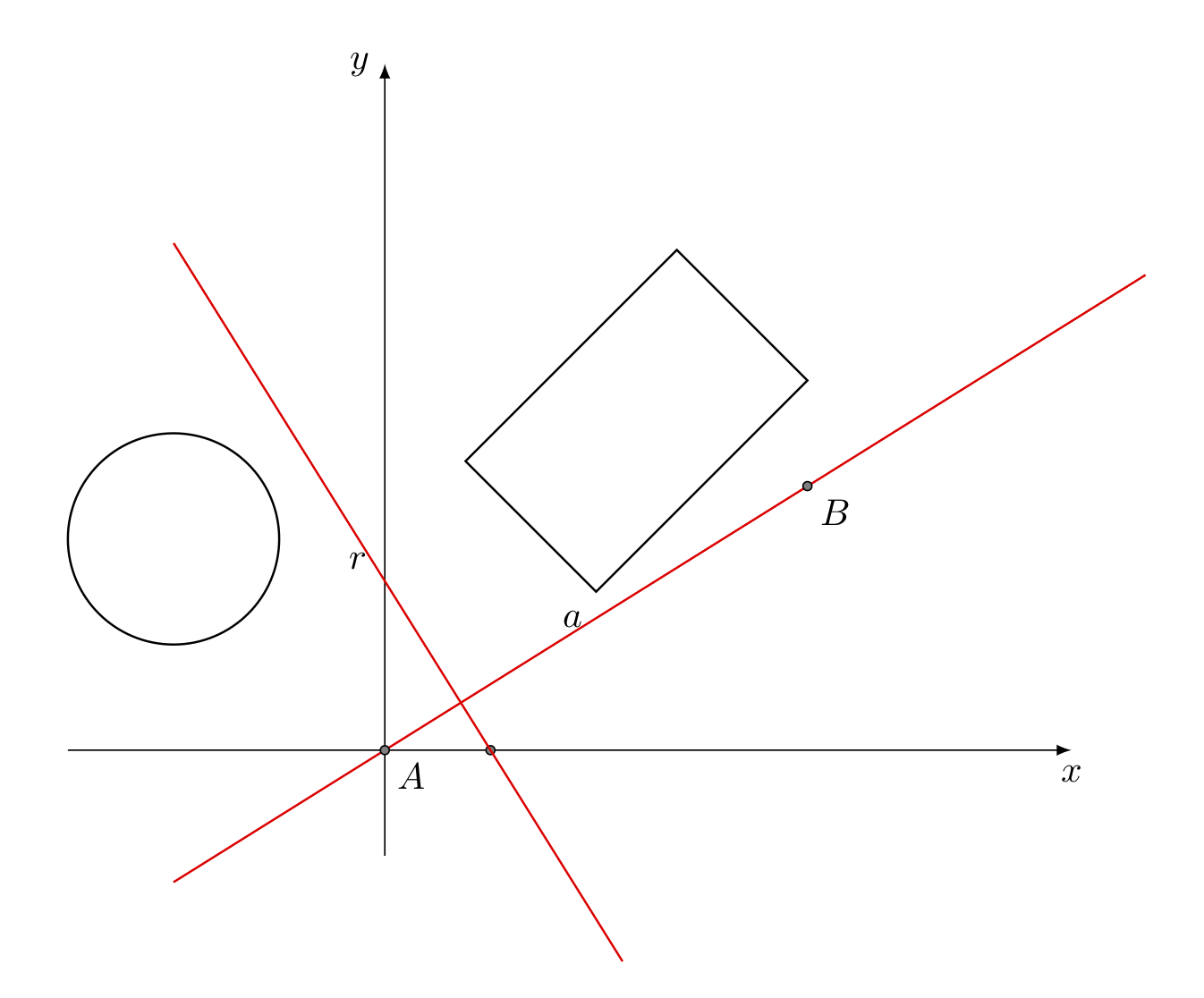
In the diagram the straight line a is the separating axis and the straight line r is the separating line. In the 3D space instead of the separating line there is the separating plane. The basic structure for the SAT algorithm in the case of two rectangles with sides parallel to the coordinate axes is the following:
SAT_Rect1Rect2(Rectangle rect1, Rectangle rect2) {
   // select two projection axis
   Vector2D axes[] = {Vector2D(1, 0), Vector2D(0, 1)};

   // loop for collision detection
   for (int i = 0; i < 2; i++) {
      if (!ControlOverlap(rect1, rect2, axes[i])) {
         // There is no collision
         return false;
      }
   }
   // There is collision
   return true;
}
The central part of the SAT algorithm is the ControlOverlap method: each call two rectangles, then it must check whether the two intervals overlap. To calculate the projection we can use the scalar product between the single axis and the four vertices of the rectangle.
In the case of rectangles oriented with respect to the Cartesian axes, the algorithm is more complex.
3) Complex collisions management
Collision management depends on the geometric shape and the number of objects in play. The problem can be treated with relative simplicity for regular geometric shapes (circles, rectangles, segments, etc.) and also in this case only if the number of objects is not high. Without these two conditions the complexity of the problem increases exponentially and becomes prohibitive, despite having great computing power at its disposal.
In all fields of science, when complexity becomes high, the only solution is to resort to approximation and optimization algorithms, which often allow a satisfactory level of precision to be achieved. Some of the approximation methods used are the following.
3.1) The bounding circle
Given a regular or non-regular geometric figure, we try to encapsulate the figure in a circle of minimal radius. The procedure requires 3 steps:
- approximate the figure with a finite set of points that follow the outline;
- determine the center of the circle starting from the set of points;
- determine the radius of the container circle, which is the maximum distance of the points from the center.
A general pseudocode of the algorithm is the following:
Circle BoundingCircle(Vector2D[] pointsList, int numPoints) {
   Vector2D center;
   float radius;
   // find the center of the bounding circle
   center = pointsList[0];
   for (int i = 1; i < numPoints; i++) {
       center = center + pointsList[i];
   }
   center = center / (float)numPoints;

   // compute the square of the radius of the circle
   radius = LengthSquared(center - pointsList[0]);
   for (int i = 1; i < numPoints; ++i) {
       float d = LengthSquared(center - pointsList[i]);
       if (d > radius) {
           radius = d;
       }
   }
   Circle circle(center, sqrt(radius));
   return circle;
}
The following animation illustrates the procedure in the case of the rectangle contained in a circle.
3.2) The bounding rectangle or box
The algorithm is similar to that of the circle. First the points of the figure are analyzed and the minimum and maximum points are determined; then we may compute the minimum rectangle that contains all the points of the figure.
The advantage of the rectangle is that it makes collision detection faster. The circle instead has the advantage of not depending on the rotation, while the rectangle needs to recalculate every time there is a rotation.
3.3) Multiple structures
In some situations the figure is not well approximated by a single circle or a single rectangle. Instead, it’s preferable to use different simple geometric figures to approximate the various parts of the figure.
For an in-depth study of collision algorithms see [1].
4) Unity’s 2D physics engine
Video games try to simulate the real world. The objects (GameObjetcs) that interact in the scene are each identified by the Cartesian coordinates (x, y, z) in the 3D space, or by (x, y) in 2D. For each object, it’s necessary to apply the laws of physics and perform the necessary calculations to determine speed, acceleration, frequency of rotation, result of impact with other objects, etc.
In the latest versions of Unity, a specific component has been added to manage the physics of objects on the 2D scene, the 2D Physics Engine. The purpose of the engine is to simulate the laws of physics, in particular Newton’s three laws of motion of mechanics.
Remember that Unity’s 2D and 3D physical engines are completely separate. The 3D engine uses the PhysX software product, while the 2D engine uses Box2D.
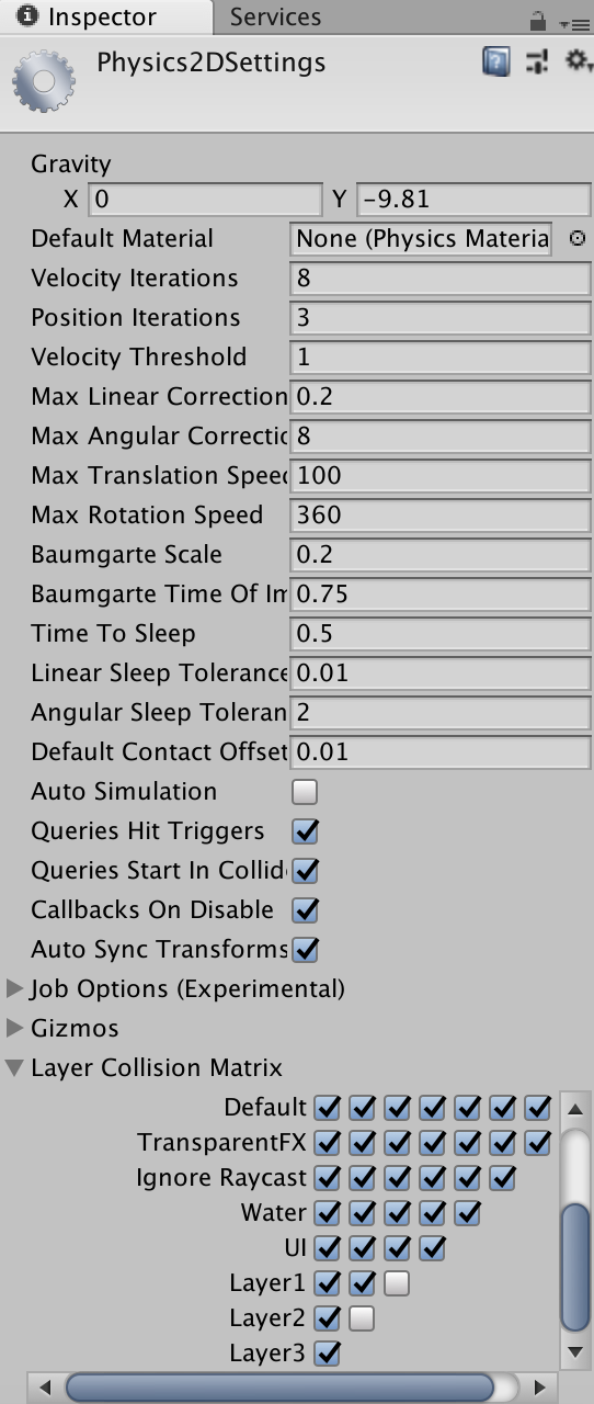
The Physics 2D engine parameters are set using the Physics 2D manager (Edit-> Project Setting-> Physics2D).
4.1) The Rigidbody 2D component
Unity 2D provides the Rigidbody 2D component, which must be associated with each object (for example a sprite) that behaves as a rigid body, subjected to force fields such as gravity. An object to which the Rigidbody 2D component is associated is placed under the control of the 2D physics engine. The Rigidbody 2D component defines physical properties such as gravity intensity, mass, friction, etc. The Rigidbody 2D objects can move only in the XY plane and can rotate around the Z axis. Anyway, Unity gives the possibility to cancel the effects of gravity for the whole scene (Edit -> Project Settings -> Physics 2D), or for a single object, by updating the Rigidbody 2D component.
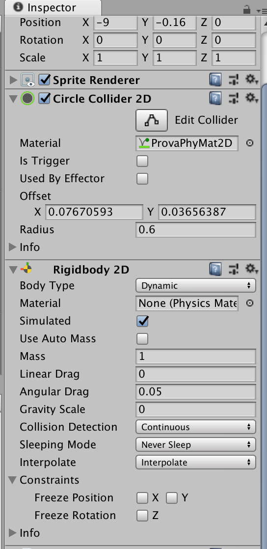
4.2) The Collider 2D component
In Unity 2D the collisions are not defined directly by Rigidbody 2D, but by new components called Collider 2D. These are components that define a region of the plane in which interaction between objects can occur. These regions generally have a different shape from the objects themselves, except in the case of objects of simple geometric shape. The Collider 3D components have extension in all three dimensions of the space, while the Collider 2D components collide independently of the position along the z axis (it’s as if they have infinite \(z\) extension). The main Collider 2D components are the following:
- Box Collider 2D – for square or rectangular shapes
- Circle Collider 2D – for circular shapes
- Polygon Collider 2D – for free shapes
- Edge Collider 2D – doesn’t require the shape to be closed
The Polygon Collider 2D allows you to create more precise colliders; using the Edit Collider option, it’s possible to modify geometric shapes by moving, adding or deleting vertices. For the complete list see the Unity User Manual.
When an object must simulate the laws of physics, such as a projectile subject to gravity, it’s necessary to associate both Rigidbody 2D and Collider 2D. In cases where you want to detect only the collision between two objects, then the Rigidbody component can be neglected, even if one of the two must still have the Rigidbody component attached (Component -> Physics 2D -> Rigidbody 2D).
There are three main types of 2D Colliders:
4.2.1) Static colliders
They do not have the Rigidbody component associated, so they are not managed by the physics engine. They are used especially for terrains, fixed walls, etc. They can interact with dynamic colliders, but they don’t move in response to collisions.
4.2.2) Dynamic colliders
The Rigidbody component is associated with them and the Inspector option isKinematic is set to false. Their movement is managed by the physical engine according to the forces and moments of force applied to them. The physical engine also manages collisions with other static, dynamic or kinematic colliders.
4.2.3) Kinematic colliders
These colliders have the Rigidbody component associated, but they have the isKinematic option in the Inspector set to true. This means that the movement of these objects is not managed by the physical engine; during collisions only the dynamic colliders will bounce. Objects with kinematic colliders do not change their speed and direction unless application instructions such as MovePosition() or MoveRotation() are executed.
4.3) Collision matrices
When two objects collide, several event management scripts are activated. The events that are generated depend on the configuration chosen for the objects in the scene. The objects, if not established otherwise, are created on the Default Layer where every one of them can collide with all the others. Except for simple cases, it is preferable to define other levels (Edit -> Project Settings -> Tag and Layers) and assign them to the various objects through the Inspector. For each new level created, a row and a column is added in the collision matrix.
In the matrix, via the editor, the collision rules can be set for the various objects associated with the different levels.
4.4) The 2D physical material (Physics Material 2D)
The 2D physical material is a component that can be associated with a GameObject to define the physical characteristics of the object itself. The physical material contains two properties: Bounciness (how much the object bounces after a collision) and Friction. A correct choice allows to simulate with greater precision the behavior of real objects in physical processes, for example in collisions with other objects.
5) Collision detection in Unity 2D
Unity provides three main methods (called callbacks) to detect collisions related to an object:
- OnCollisionEnter2D – called when a collider/rigidbody comes into contact with a rigidbody/collider
- OnCollisionStay2D – called until the collider is inside the contact area
- OnCollisionExit2D – called when the collider leaves the contact area
The three methods are called by Unity in the physical engine cycle (fixed time step). They are activated only on the object that has the Rigidbody 2D component.
using UnityEngine;
using System.Collections;
using UnityEngine.EventSystems;
using UnityEngine.UI;

public class BoxColliderScript : MonoBehaviour {
    void OnCollisionEnter2D (Collision collisionInfo) {
         Debug.Log("Enter collision");
    }
    OnCollisionStay2D(Collision collisionInfo) {
         Debug.Log("Stay Collision");
    }
    void OnCollisionExit2D (Collision collisionInfo){
        Debug.Log("Exit collision");
    }
}
6) Trigger colliders
Triggers are a special type of collider. To activate them, set the isTrigger option in the Inspector. With this option, the collider is ignored by the physical engine. So, the triggers do not physically collide with other objects, but only detect the passage of every other collider within their potential collision zone, allowing the application to perform any processing based on the events. Unity records events and calls the following methods, which can be managed by the application in the script linked to the object containing the collider:
- OnTriggerEnter2D – when the collider enters the area of a trigger
- OnTriggerStay2D – when the collider remains inside the trigger
- OnTriggerExit2D – when the collider exits the trigger
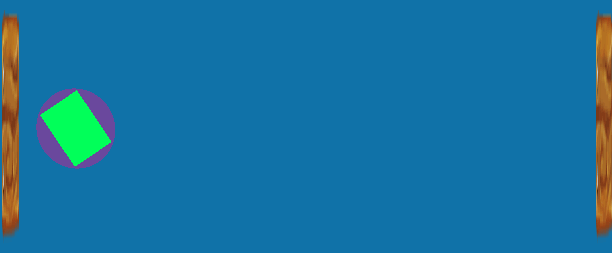
The following image shows a ball with the 2D circle collider moving horizontally between three walls.
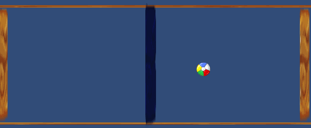
The ball has also the Rigidbody component associated, with the intensity of gravity (Gravity Scale) set to zero. The external walls have only the static 2D collider, while the intermediate one has a 2D collider trigger. When the ball approaches the external walls, the collision occurs and the OnTrigger events are activated. Unity’s physics engine applies the laws of mechanics, in particular the principle of conservation of the quantity of motion, according to which at the moment of impact with the right and left walls the ball reverses the direction of 180 degrees, always maintaining the horizontal movement.
When the ball passes through the intermediate wall no collision occurs, but the onTrigger events are activated. In the case under examination, on the occasion of the onTriggerEnter2D event, a red color is set with a script associated with the ball object, while the onTriggerExit2D event is set to blue.
Conclusion
Collision management is present in most video games: collisions between characters, between an object and a wall or a floor, between a projectile and a target, etc. In many successful video games, such as Super Mario Bros, the correct handling of detection and collision response plays a fundamental role. It’s essential for game developers to understand the theoretical aspects and also the possible limitations of physical engines.
In this article we discussed the case of collisions in the two-dimensional environment. In a future article we will describe the management of 3D collisions, both in their mathematical aspects as well as in the context of the Unity 3D physics engine.
Bibliography
[1]C. Ericson – Real-Time Collision Detection (Morgan Kaufmann)


0 Comments